555 Timer IC Testing Circuit
NE555 timer IC is a 8 pin dip package IC which performs array of timing tasks in the electronic circuits. There is a huge list of experiments which can be performed with 555 IC, that’s why it is very popular among electronics hobbyists. But before using the IC, one should check it that it is working properly or not. So we have described a simple circuit through which you can test 555 timer ic
This simple 555 IC testing-circuit tests your entire 555 timer IC, so before using your IC check immediately that your IC is good or bad by checking it. This can be done by checking the IC that is it is oscillating or not. Or you can use this circuit in some other circuits also to troubleshoot the proper working of 555 IC. This tester will rapidly tell you if the timer is functional or not. Important feature of this circuit is it will tell 555 timer is shorted or it is not oscillating. Assemble the circuit properly as shown in circuit diagram.
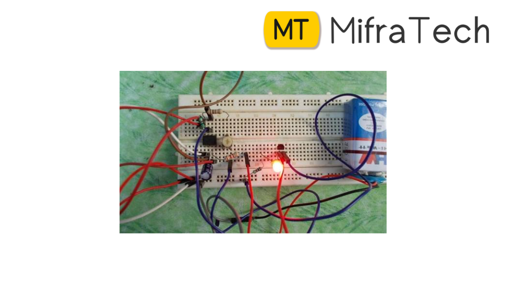
First of all insert the IC in socket very carefully so that no pin of 555 timer get damage. Now to see the result, switch on the power supply. If your 555 timer is working properly, both the LED1 and LED2 will glow. And any of the LEDs is off or both LED1 and LED2 are not glowing means your 555 timer IC is faulty
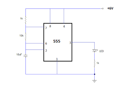
Working of 555 Timer IC Circuit: In this circuit, we have used the NE555 IC as an astable multivibrator and when power is provided to circuit, the LEDs will start blinking which will show that the IC is working. The blinking rate of LEDs can be changed by increasing or decreasing the values of resistor R1 and R2 and capacitor C1. You can calculate the time duration with the help of formula given below: T = 0.7(R1+2R2)*C1 in seconds. As soon as power supply is provided, C1 will start charging through R1and R2.When the voltage across C1 rises above 2/ 3 of supply voltage, the internal Flip Flop toggles. As a result, pin 7 becomes low and C1 starts discharging. When the voltage across C1 goes below 1/ 3 of supply voltage, the internal Flip Flop resets and pin 7 goes high. The C1 again starts charging. All this will happen only when your IC is in good condition. According to the frequency as set with the help of resistor R1, R2 and capacitor C1 charging and discharging take place and LED1 and LED2 will flash accordingly. From these observations, we can conclude that IC NE555 is faulty or not.