ABSTRACT
Induction motors are widely used in industries and most times get burnt upon the start of the motor. This project is designed to provide low voltage start to induction motors. This is achieved by using star to delta conversion. Star/Delta starters are probably the most common reduced voltage starters in the 50 Hz industrial motors. Star-delta is used to reduce the start current applied to the motor then after some time full load current is applied to the motor. Since in star connection current is same in different phases while line voltage is the root three times the phase voltage. The voltage is reduced if the induction motor is started as star. In delta connection the voltage is same as that of phase voltage so full voltage is applied if we run the motor as delta connection. In this project, an automatic star-delta starter was designed using electrical relays and an electronic timer. By feeding the motor with (58%) of the full load current to limit the starting current surges by starting the motor at reduced voltage and then have full supply voltage reconnected when they run up to near rotated speed. This method is commonly referred to as “Soft starting” the motor.
INTRODUCTION
Most of the machines used in the industries are three phase induction motors. They have simple and rugged construction and their robust nature make them possible to operate in all environmental condition. Induction machines are cheaper in cost and maintenance free, have starting torque and are widely used in domestic and industrial applications. During starting of an induction motor, the starting current is around eight to ten times the rated current and this persists for a few cycles. This may be very much damaging for the machine, causing a disturbance of voltage on the supply lines due to large starting current surges. To limit the starting current surges, large induction motors are started at reduced voltage and have full supply voltage reconnected when they run up to near rotated speed. These forms of starters are known as reduced mechanical starters, they are used to replace the direct-on-line starters. This is because of their controlled starting capability with lower starting current during the soft start period (Suvra,2014). Voltage reduction during star-delta starting is achieved by physically reconfiguring the motor winding. During starting, the motor windings are connected in star configuration and this reduces the voltage across each winding. This also reduces the voltage by a factor of three. After a period, the windings are reconfigured as delta and the motor runs normally. The stardelta starter is generally obtained from three contactors: electromechanical timer and a thermal overload relay for operating a 3-phase motor at 440 volts at ac mains supply of 50 Hz. The current through the windings are (58%) of the current in the line. The star-delta starter is simple and rugged, relatively cheap compared to other reduced voltage methods with good torque and current performance (Thompson, 2017). Star-Delta Starter Star/Delta starters are the most reduced voltage starters in the 50 Hz frequency (known as Wye/Delta in the 60 Hz world). They are used to reduce the start current applied to the motor during start as a means of reducing the disturbances and interference on the electrical supply. In star-delta starting method, the wiring connection from the power supply source to the motor is connected from star to the delta connection. With star connection, the motor takes 58 % less voltage. However, as the torque is proportional to square of the voltage, the starting torque also reduces (Ferraris, 2003).
Reasons for using star-delta starter
The Star-Delta starter is preferred over the othe to the following
Starting current is reduced 3-4 times of the di due to which voltage drops and hence it causes less loses.
The operation on the star-delta is simple and rugged.
Good torque/current performance.
Star-delta circuit comes in circuit first during starting of motor, which reduces voltage 3 times current also reduces up to 3 times and hence less motor burning is caused.
The disadvantage of using star-delta starting is the huge reduction in the starting current of the motor, which will result in a significant cost saving of cables, transformers, and switchgears.
Current Surges in Star-Delta At changeover from star to delta, a current surge will arise almost as high as the corresponding Direct process takes place at a low speed. This type of star starter is called open transition, can have a momentary hitch operation, allowing a momentary inrush of current. Also, during the period of switchover from star to delta connection, the motor speed reduces rapidly, which also calls for higher current pulse after connection to delta. Automatic Star/Delta Starter Due to the afore mentioned short comings of the above starting methods, there is need for further research to correct these inadequacies.Hence, the automatic star relays and adjustable electronic timer. The automatic star starter makes use of a more advanced hardware and software components than the native star further to correct the current surge problem of the open transition starting by making useof an additional contactor and as set of resistors to keep the motor on transition, this is known as closed transition.
Hardware Components
1. TRANSFORMER (230 2. VOLTAGE REGULATOR (LM 7805) 3. RECTIFIER 4. FILTER 5. RELAY 6. INDUCTION MOTOR 7. 555 TIMER 8. BC 547 TRNSISTOR 9. BC 558 10. IN4007 RECTIFIER DIODE 11. LED 12. RESISTOR 13. CAPACITOR The control of an automatic Star adjustable electronic timer for induction motor comprised of the following stages
Power Supply -The three-phase of an AC source Transformers Input stage: the input stage comprised of the star/delta configuration relays. Control stage is made up of electronic adjustable timers. Output stage consists of the motor system. , July, 2020 39208 | P a g e Delta Starting At changeover from star to delta, a current surge will arise almost as high as the corresponding Direct-On-Line value if the process takes place at a low speed. This type of star-delta starter is called open transition, can have a momentary hitch in operation, allowing a momentary inrush of current. Also, during the period of switchover from star to delta connection, the motor speed reduces rapidly, which also calls for higher current pulse after connection to delta. Automatic Star/Delta Starter Due to the afore mentioned short comings of the above starting methods, there is need for further research to correct these inadequacies.Hence, the automatic star-delta starter using relays and adjustable electronic timer. The automatic star-delta starter makes use of a more advanced hardware and software components than the native star-delta starters and it went further to correct the current surge problem of the open transition starting by making useof an additional contactor and rs to keep the motor on-line during the transition, this is known as closed transition. MATERIALS AND METHODS TRANSFORMER (230 – 12 V AC) VOLTAGE REGULATOR (LM 7805) INDUCTION MOTOR BC 547 TRNSISTOR IN4007 RECTIFIER DIODE.
The Power Supply Unit This makes use of three phase system connected to the motor and the transformers. The 3 step-down transformers, the primary of which are connected in star mode while their secondary develop filtered dc after passing through respective bridge rectifiers and filtered capacitors. The main contactor connects the reference source voltage R, Y, B to the primary terminal of the motor U1, V1, W1. In operation, the main contactor and the star contactor closed initially, and afterwards, the star contactor is opened, and the delta contactor is closed (Terrel, 2013) The Input Unit These relays are the star connected relays, which are used to switch on the motor, using low voltage. This voltage is reduced by a factor of 0.58.Two of the rectified dc voltages from the source are connected to the relay to serve as input to it. The R, Y, B are the three phase line voltages which are given to the primary electrical relay. The main motor coils are U, V and W, in the star mode of the motor windings, the primary electrical relay connects the mains to the U1, V1, and W1. The star connected relay shorts the U2, V2 and W2. Control Unit The control unit is the adjustable electronic timer which is used to switch operation from Star to Delta connections. The electronic timer is the 555-timer connected in the monostable configuration. The timing or delay is achieved from the RC oscillator connected to the 555-timer. The RC oscillator is resistor 1k, 10k pot and the 470µ capacitor. When the circuit is turned on, the timer allows the star connected relay to turn on. The output of the 555-timer (pin 3) is connected to the NPN transistor (BC547), this is used to swit relays connected in Star configuration for a timing. After the time delay elapsed, the BC547 transistor will switch off and the PNP transistor (BC558) will switch on. The conversion from star to delta enables the motor running on the star mode with a decreased voltage and current producing less torque, and the delta mode enabling the motor run on its full power, utilizing high voltage and current to transform a high torque (Nevelsteen et al, 1989).
RESULTS AND DISCUSSION
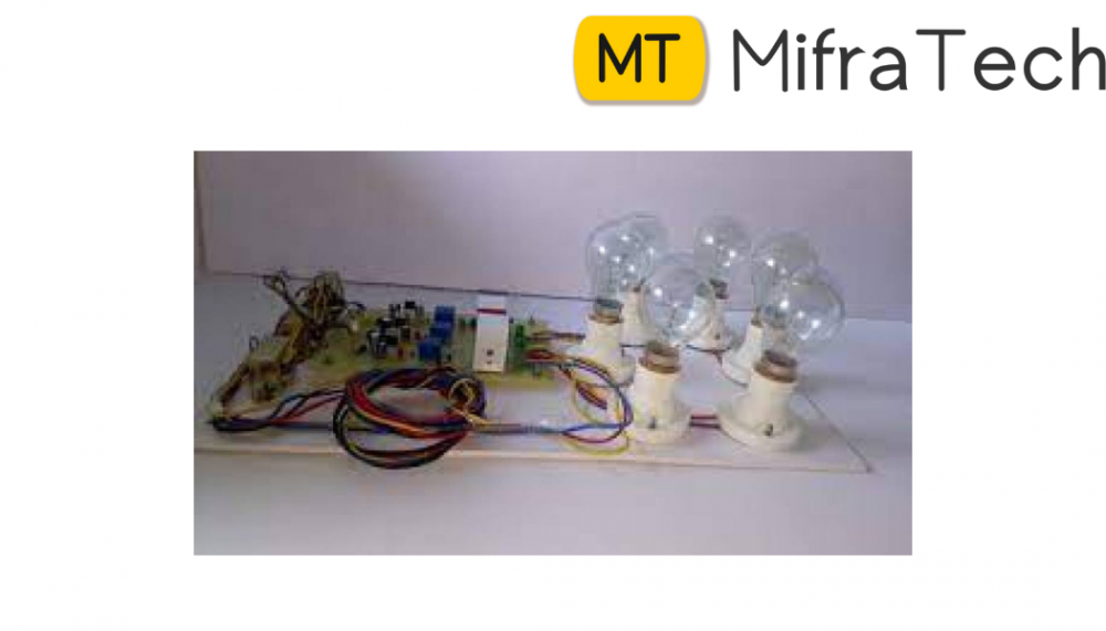
Continuity Test The continuity test was performed by placing a small voltage (wired in series with a LED or noise-producing component such as a piezoelectric speaker) across the chosen path. If electron flow is inhibited by broken conductors, damaged components, or excessive resistance, the circuit is "open". The devices that was used to perform this test include multi meters which measure current and specialized continuity testers which are cheaper, more basic devices, generally with a simple light bulb that lights up when current flows. This test was performed just after the hardware soldering and configuration has been completed. This test aims at finding any electrical open paths in the circuit after the soldering. Often, the electrical continuity in the circuit is lost due to improper soldering, wrong and rough handling of the PCB, improper usage of the soldering iron, component failures and presence ofbugs in the circuit diagram. A multi this test. It was kept in a buzzer mode and then conn ground terminal of the multi meter to the ground, both terminals across the path that needs to be checked was connected. If there is continuation, then you will hear the beep sound (Andreas, 2010). POWER-ON TEST This test was performed to ch terminals meets design specification. The multi in voltage mode and the test performed without ICs. Firstly, the transformer was checked if the required +12V ac output voltage was achieved (depends on the tran If a battery was used, it will check if it is fully charged or not according to the specified voltage of the battery by a multi meter. The voltage achieved was applied to the power supply circuit. This test was done without ICs because if there is any excessive voltage, this may lead to damaging the ICs. If a circuit consists of voltage regulator then the input to the voltage regulator will be checked (7805, 7809, 7815, 7812, 7915), if the required input is +12V, the required output can be obtained depending on the regulator used in the circuit. Forinstance, 7805 will bring an output of 5V while 7809 will produce +9V at output pin and so on. This output from the voltage regulator is given to the power supply pin of specific ICs. Hence the voltage level at those pins were checked if the required voltage was gotten. Similarly, check for the other terminals for the required voltage was carried out. There was an assurance that the voltage at all the terminals is as per the requirement. When the circuit was connected to 3 the six lamps glowed with low intensity. This was caused by the line voltage which is the voltage between two given phases has a value of 440volts, because each phase voltage which is the voltage between a given phase and neutral has a voltage value of 220 volts.
CONCLUSION
The starting current of an induction motor is around eight to ten times the motor rated current. The high current persists for a few cycles. Since the windings of the motor are designed to carry maximum of rated current, this high current during starting of the induction motor can cause damage. Hence, the authors are motivated to solving this problem. This paper presents a design and construction of an automatic star-delta starter to limit the starting current of the induction motor with the use of reduced starter. Automatic star/delta starter using relays and adjustable electronic timer is used and the starting current and torque is limited to one-third as compared to nine times in open loop
embeeded and electronics projects
embedded electronics projects
embedded systems final year projects
embedded based final year projects
embedded related projects
embedded project
embedded projects for ece
embedded system projects for ece
embedded systems mini projects for ece
embedded based projects for ece
embedded systems projects for eee
embedded project ideas
embedded systems final year project ideas
embedded system based final year projects
embedded project topics
embedded final year projects for ece
best ai projects for beginners
https://www.mifratech.com/public/
https://www.facebook.com/mifratech.lab
https://www.instagram.com/mifratech/
https://twitter.com/mifratech