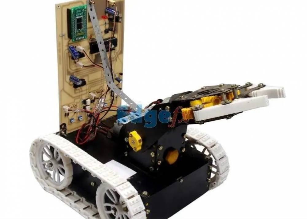
The system provides a pick and place robotic arm which is a soft catching gripper system. It can be used to pick and place objects as needed. This arm is mounted on a robotic vehicle that can be controlled wirelessly through an android mobile phone.
The android phone acts as the controller used to transmit the control commands through Bluetooth. These commands are used to operate the robot front, backwards, left and right directions. At the receiver side four motors are used, two to drive the vehicle and the other two used to control the arm movement and gripper movement respectively.
The android phone is used as remote controlling device used to control the robotic vehicle. The use of Bluetooth technology provides adequate operational range with instant transmissions. The microcontroller after receiving these commands, operate required motors through the driver IC. It can be remotely controlled by any android device.
This robotic vehicle may be used in industrial or even domestic purposes and even as a help for industrial workers.
Block Diagram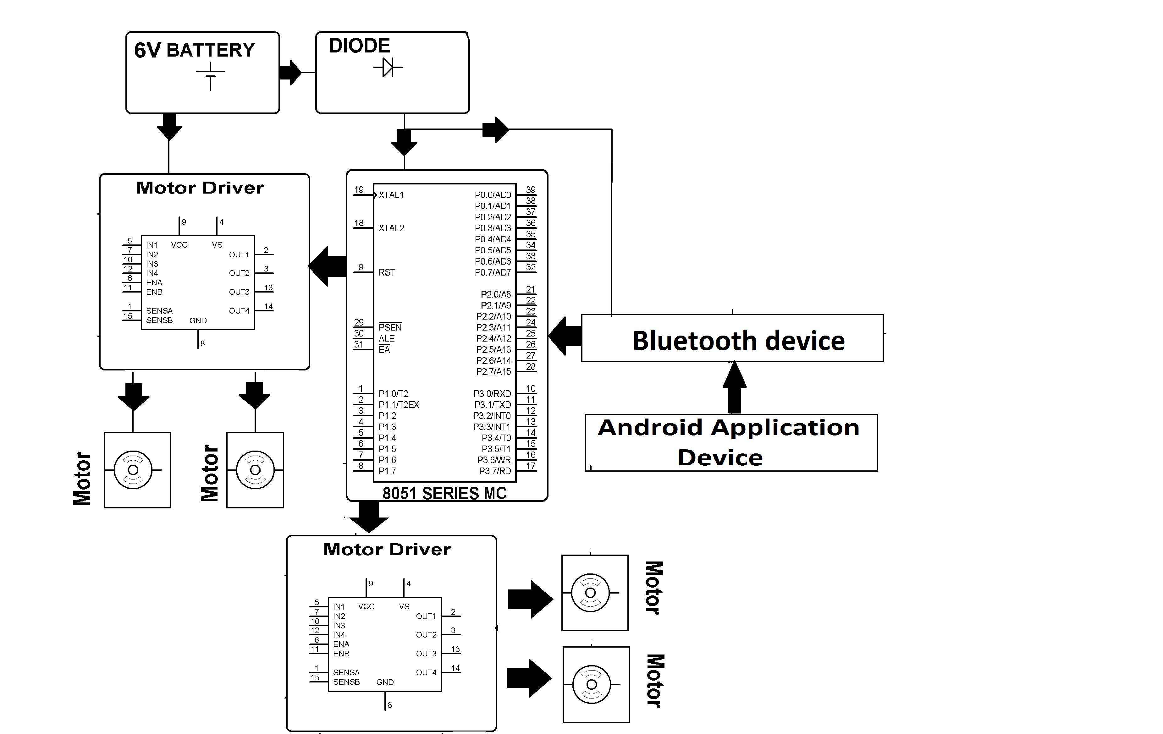
The project is designed to develop a pick n place robotic vehicle with a soft catching gripper. The project is aimed to design and develop a pick and place robotic vehicle with a catching gripper. The project will include development of an android app and mobile robot which will be able to move objects from one place to another. Thus, controlling the vehicle remotely. Remote operation is achieved by any smart-phone/Tablet etc., with Android OS; upon a GUI (Graphical User Interface) based touch screen operation. This prototype will pave path for real life models using the same concept.
The vehicle will be controlled by the android application device at the transmitting end, which will send signal i.e. ASCII code, to Bluetooth module (HC-05) which is employed as an interface between Mobile and vehicle (robot). The microcontroller is coded using AVR Studio for controlling of the motors, both to move the robotic vehicle and to control the gripping of the objects through the arm. At the transmitting end using android application device, commands are sent to the receiver to control the movement of the robot either to move forward, backward and left or right etc. At the receiving end four motors are interfaced to the microcontroller where two for them are used for arm and gripper movement of the robot while the other two are for the body movement. The android application device transmitter acts as a remote control that has the advantage of adequate range, while the receiver end Bluetooth device is fed to the microcontroller to drive DC motors via motor driver IC for necessary work. Remote operation is achieved by any smart-phone/Tablet etc., with Android OS; upon a GUI (Graphical User Interface) based touch screen operation. The main advantage of this robot is its soft catching arm that is designed to avoid extra pressure on the suspected object for safety reasons.
2. Block Diagram
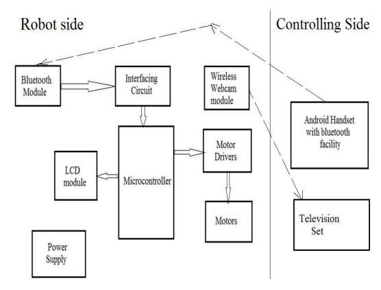
The project contain 2 sections
1. Robot (Receiver end)
2. Control section (Transmitting end)
It consists of an Atmega16 Micro controller IC, Bluetooth module, four DC Motors with driver IC and power supply. The pick and place robotic arm consists of a robotic arm placed on a moving vehicle. The vehicle is able to move along any type of surfaces irrespective of its smoothness or roughness. It uses two motors for the operation and a belt type tyre is attached to the vehicle like in the tanks, for the smooth and reliable operation. The pick and place robot uses four motors for the operation of the system, two for the operation of moving vehicle and two for the pick and place operation. The pick and place arm consists of an arm assembly with a jaw, which is only able to move in up and down direction. There are two motors for the arm assembly, one for the up and down motion and other for jaw opening and closing.
The maximum upward and downward motion is limited by a mechanical push button type switches. It breaks the motor circuit when the arm is at its maximum position beyond which the motor does not rotate. For the controlling of motor, motor driver IC and Atmega328 micro controller is used. The input signal or controlling signal is given from an android device, which is interfaced with the microcontroller by a blue tooth module. L293D has 2 set of arrangements where one set has input 1, input 2, output 1 and output 2 and other set has input 3, input 4, output 3 and output 4. The program is so written i.e., while executed it sends commands to the motor driver IC as per its requirement for running the motor for the movement of the robot as explained in the subject above in L293D. The android phone screen is used for sending commands for left, right, forward and backward and centre is for stop through its inbuilt Bluetooth system. 12V battery powers the circuit in series with a diode D2 that nearly provides 5 through regulator IC LM 7805 for the microcontroller which has standard connections like crystal, reset arrangement indication LED etc. A blue tooth device being powered from a reversed biased Zener diode D1, is interfaced to the microcontroller that after being paired with any smart phone communicates with this Bluetooth device for taking appropriate action as per the touch operation made on the smart phone.
The work uses another motor driver IC working on similar technology for the arm up and down / open and close duly interfaced to the microcontroller with duly pulled up resistors. The program is so written that for touch screen operation from the smart phone results in command being sent through the Bluetooth module, on A=open, B=close, C=up and D=down number upon MC developing appropriate rotation of the motor. Now we consider the operation of the soft catching arm. It senses pressure in the arm by measuring current. The motors used for an operation up and down and gripper operation open and closed pass through series resistor of 10 ohms/ 2 watt from the output of the second motor driver IC L293D.While motor is operating the returning current from Driver IC is grounded through this resistance. And the voltage across it is proportional to the current owing through it and this current is proportional to the load at the motor or pressure in the arm jaws. Thus by measuring the voltage we can measure the amount of pressure. The inbuilt ADC in the Atmega328 continuously measuring this voltage.
Thus, while motor operates in normal condition the running current results normal voltage drop across the 10R/2W ohm resistor as the motor can run in clockwise (or)anti-clockwise. When load increases the voltage across resistor get increased and is continuously monitored by micro controller. When it increases above a certain value, interrupt is produced thus stopping the motor. The program is so written that once interrupt zero occurs low, no such command would generate any input to the motor driver IC for any direction for that motor movement. Only
ATMEGA16A Microcontroller : To define the task of the four motors. To start or stop a motor according to the commands obtained from the android application device using a bluetooth module
Bluetooth Module (HC-05) : To establish a connection between the android application device and the circuit. It basically incorporates a serial communication between the android application device and the circuit.
L293D motor driver IC : It is a motor driving IC. We are using two L293D which can inculcate the working of two motors each. Since we need three motors, we are using two motor driving ICs.
7805,5V regulator IC : The various components used in the circuit operate at a voltage 5V but the input supply may be of either 12V or 9V. hence, we use a 7805 voltage regulator IC to convert the input voltage into desired voltage
Note : Find the best solution for electronics components and technical projects ideas
keep in touch with our social media links as mentioned below
Mifratech websites : https://www.mifratech.com/public/
Mifratech facebook : https://www.facebook.com/mifratech.lab
Mifratech instagram : https://www.instagram.com/mifratech/
Mifratech twitter account : https://twitter.com/mifratech
Contact for more information : [email protected] / 080-73744810 / 9972364704