Audio Tone Control Circuit
Various audio tone control circuits have been developed since the evolution of electronic audio systems. Some are being developed as passive tone control and some are active. The difference between them lies in the amplification and attenuation of the signal. An audio tone control circuit with an amplifier integrated with it is called ACTIVE tone control circuit and in the absence of the amplifier it is PASSIVE which degrades the signal strength. Now the need for a tone control for an audio signal may be for two reasons. First is the controlling of the BANDWIDTH of the signal entering the audio POWER amplifier. Without limiting the bandwidth up to certain level the signal may not be possible to recollect at the speaker faithfully. But today’s audio IC manufacturer has taken care of it. So we are free. The second reason is for our own satisfaction with the music. Tone control is the act of controlling the frequency to be amplified by the amplifier. So a tone control circuit is always followed by a POWER amplifier. A single audio signal consists of various frequencies mixed in it. The low frequencies are known as BASS and the high frequencies are known as TREBLE. While separating the frequencies the application of tone control circuits take place. Now coming to the point of designing the circuit. Here an active tone control circuit has been designed for the BASS and TREBLE only and if needed the circuit can be extended for various bands.
Working & Components
OPERATION
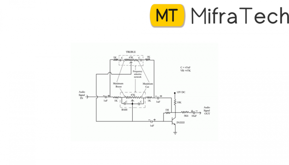
The amplifier built around the transistor is in common-emitter mode and is an inverting amplifier i.e. the audio signal at the output of the amplifier is 180 degree out of phase with the signal at the input. So when the output is allowed to collide with the input by the process of FEEDBACK, they cancel each other leaving no signal at the input of the amplifier. But for a selective cancellation of the frequencies, a RC circuit has been connected at the feedback part of the amplifier to cancel the UNWANTED frequencies. It is also possible to connect the RC circuit only at the input without taking any feedback from the amplifier but positioning the RC circuit at the FEEDBACK of amplifier greatly increases the STABILITY of the circuit. The wiper of the potentiometer connected at the RC circuit can be positioned at desired places to have different frequency cancellation thus allowing only the desired frequencies to enter the amplifier.
COMPONENTS
1. Transistors (2N2222)
2. Variable Resistor (50K)
3. Capacitors (1uF [3], 10uF [1]) Electrolytic
4. Capacitors (47nF [4]) Ceramic
5. Resistor (1K [4], 10K [1], 5.6K [1], 1M [1])
POWER SUPPLY
12V regulated DC power supply. LMPS is more preferable than SMPS.