Here is a High current charger for Fast charging sealed lead acid batteries used in Automobiles, Inverters etc. This charger can give 5 Ampere current for quick rejuvenation of the battery. It uses an Adjustable voltage regulator so that 6 volt and 12 volt batteries can be charged.
LM338K is a high current variable voltage regulator that can provide 2 to 25 volts DC with high current output. It’s important features are 7 Ampere peak output current, adjustable output down to 1.2 volts, thermal regulation etc. It is easy to use and require only 2 external resistors to set the output voltage. The time dependent current limiting ability of the device allows peak current of up to 12 ampere to be drawn for short time. So that it is useful in heavy transient loads and speed start up.
Use of external resistors
LM338 K is available in metal can package TO3. K suffix metal can. It has only two pins – Vin and Adjust. The body of the device acts as the output pin. On the bottom side, the first pin is adjust and the second pin is Vin. LM338 requires heat sink to dissipate heat since it is draining high current. Two resistors are required to set the output voltage. Resistor R1 (220 Ohms) act as the programme resistor. Usually 1.25 volts reference voltage (Vref) develops between the output and adjusts pins. The reference voltage is impressed across the programme resistor R1. The voltage across R1 is constant so that constant current flows through the output set resistor VR1.Therefore output voltage is
Vout = Vref (1 + VR1 / R1) + I Adj VR1
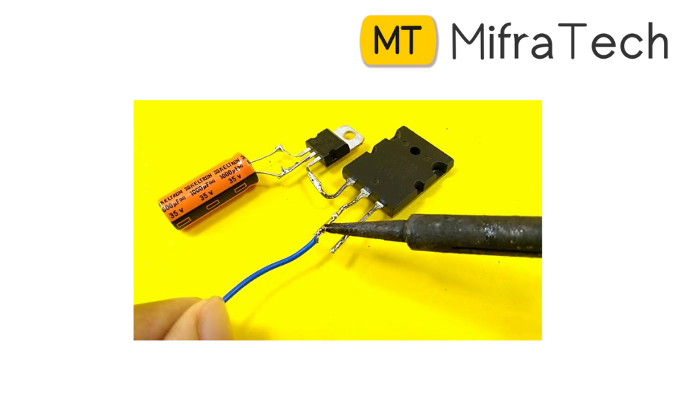
Use of capacitors
Two capacitors are usually soldered close to the input and output terminals. C2 is the input bypass capacitor. Output capacitor C3 gives stability for the output current.
Circuit operation
Input voltage is obtained from a >15-0-15 volt 5 Ampere secondary transformer with rectifying diodes D1 and D2. Capacitor C1 makes the DC ripples free and around 16 volt DC enters into the Vin input of the regulator. VR1 can be used to set the output voltage from 2 volts to 25 volts. A digital panel meter is used for measuring the output voltage. Ready made LED or LCD panel meters are available at reasonable cost. This can be directly connected to the output. So by adjusting VR1, it is easy to see the output voltage in the meter. If the output put voltage reduces due to line voltage drop, it can be easily detected through the panel meter. The panel meter also can be used to measure the terminal voltage of the battery. If the power supply is switched off, meter shows the terminal voltage. If the voltage remains steady, it indicates that the battery is fully charged and holding charge. Easily available IN 5402 diodes are rated at 3 Amps so if the device become too hot, use a 10 A KBPC 1000 Bridge rectifier.
Setting the output voltage
A fully charged 12 volt battery should have a terminal voltage of 13.5 volts and that of a 6 volt battery 6.5 volts. To charge the battery, set the output voltage for charging as 14 volts for 12 volt battery and 8 volts for 6 volt battery.