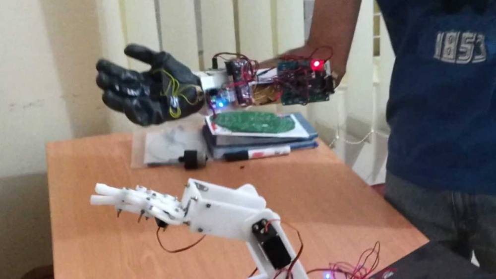
Hand Motion Controlled Robotic Arm
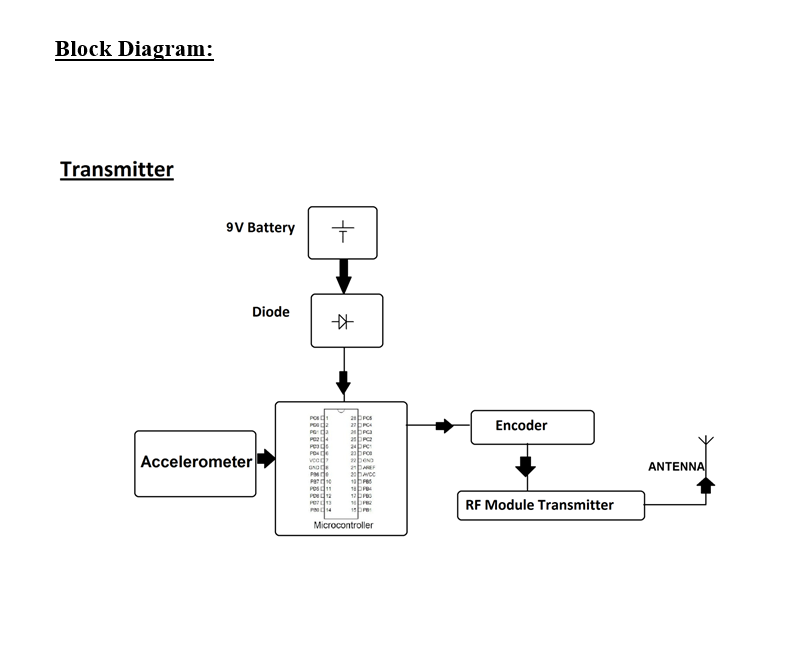
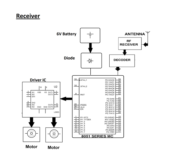
This system allows controlling a robotic arm by hand movements. This system uses RF receiver which is interfaced to the 8051 microcontroller which controls the driver IC which is responsible to control the movement of the arm. The transmitter circuit consists of an accelerometer sensor which is interfaced to the Atmega microcontroller.
The transmitter circuit sends commands to the receiver circuit. This commands indicates whether to move the robotic arm in upward or downward direction or whether the commands indicates to grip an object or release it.
Hardware Specifications
Software Specifications
What’s an accelerometer measure? Well, acceleration. You know…how fast something is speeding up or slowing down. You’ll see acceleration displayed either in units of meters per second squared (m/s2), or G-force (g), which is about 9.8m/s2 (the exact value depends on your elevation and the mass of the planet you’re on).
Accelerometers are used to sense both static (e.g. gravity) and dynamic (e.g. sudden starts/stops) acceleration. One of the more widely used applications for accelerometers is tilt-sensing. Because they are affected by the acceleration of gravity, an accelerometer can tell you how it’s oriented with respect to the Earth’s surface. For example, Apple’s iPhone has an accelerometer, which lets it know whether it’s being held in portrait or landscape mode. An accelerometer can also be used to sense motion. For instance, an accelerometer in Nintendo’s Wii-mote can be used to sense emulated forehands and backhands of a tennis racket, or rolls of a bowling ball. Finally, an accelerometer can also be used to sense if a device is in a state of free fall. This feature is implemented in several hard drives: if a drop is sensed, the hard drive is quickly switched off to protect against data loss.
Now that you know what they do, let’s consider what characteristics you should be looking for when selecting your accelerometer:
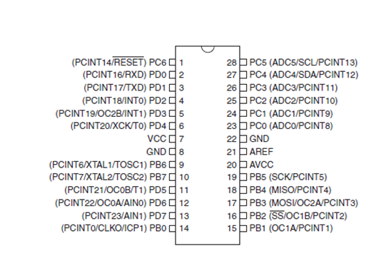
ATmega328
The Atmel 8-bit AVR RISC-based microcontroller combines 32 KB ISP flash memory with read-while-write capabilities, 1 KB EEPROM, 2 KB SRAM, 23 general purpose I/O lines, 32 general purpose working registers, three flexible timer/counters with compare modes, internal and external interrupts, serial programmable USART, a byte-oriented 2-wire serial interface, SPI serial port, 6-channel 10-bit A/D converter (8-channels in TQFP and QFN/MLF packages), programmable watchdog timer with internal oscillator, and five software selectable power saving modes. The device operates between 1.8-5.5 volts. The device achieves throughputs approaching 1 MIPS per MHz.
Ø High Performance, Low Power AVR® 8-Bit Microcontroller
– Advanced RISC Architecture
– 131 Powerful Instructions
– Most Single Clock Cycle Execution
– 32 x 8 General Purpose Working Registers
– Fully Static Operation
– Up to 20 MIPS Throughput at 20 MHz
– On-chip 2-cycle Multiplier
Ø Flash Program Memory: 32 kbytes
Ø EEPROM Data Memory: 1 kbytes
Ø SRAM Data Memory: 2 kbytes
Ø I/O Pins: 23
Ø Timers: Two 8-bit / One 16-bit
Ø A/D Converter: 10-bit Six Channel
Ø PWM: Six Channels
Ø RTC: Yes with Separate Oscillator
Ø MSSP: SPI and I²C Master and Slave Support
Ø USART: Yes
Ø External Oscillator: up to 20MHz
Note : Find the best solution for electronics components and technical projects ideas
keep in touch with our social media links as mentioned below
Mifratech websites : https://www.mifratech.com/public/
Mifratech facebook : https://www.facebook.com/mifratech.lab
mifratech instagram : https://www.instagram.com/mifratech/
mifratech twitter account : https://twitter.com/mifratech
Contact for more information : [email protected] / 080-73744810 / 9972364704