Summary:
The smart alarm clock is an open-source project about building and programming an Internet of Things alarm clock. The following project provides all information you need to build the smart alarm clock. The IoT Smart Alarm Clock has text to speech synthesizer, three ways of wake-up sound, set alarm via smartphone or any other computer, running apache2 server, automatic, display brightness adjustment, audio amplifier volume control, 3D-printable case, case built-in tactile switch, alphanumeric display shows text, and 3W speaker definitely wakes you up.
II. Objectives :
The purpose of this project is to build an IoT Smart Alarm Clock. The project is designed to help students develop practical IoT device knowledge
III. Industry-Based Applications Digital Logic Design is the representation of signals and sequences of a digital circuit through numbers. It is the basis for digital computing and provides a fundamental understanding on how circuits and hardware communicate within a computer. Digital logic is typically implanted into most electronic devices, including calculators, computers, video games, and watches. This project introduces how to connect IoT (internet of things) devices to circuitry. This may relate to a professional engineering job by an engineer may design smart devices. Many engineers may get in this field with the evolution of smart products, such as smart lights, smart homes, smart appliances, smart televisions, smart phones and more.
B. Procedure a. Raspberry Pi Zero Running Raspbian i. In order to complete this project, you need to set up a Raspberry Pi running Raspbian (Lite), the Debian version of Raspberry Pi. Sure you might use different Raspberry Pis and a different OS, but therefore you might need to modify your system somewhat. For example, if you want to use Raspberry Pi 3 you don't have to buy and use an additional WiFi-stick, might just use the on-board audio output, but might not be able to use the given 3D-printable case. So by changing some parts of this project you got to keep in mind that this instruction is based on using Raspberry Pi Zero
Installing Raspbian ii. First visit the Raspberry Pi downloads page and download the latest Raspbian Lite image. We decided to work with the Lite version, since this project has no need for a graphical user interface. Now follow the instructions page of how to download and write the Raspbian image to your sd-card. Once your sd-card is set up, plug it into your Pi and connect mouse, keyboard and screen to the Pi.
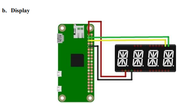
i. This step contains the soldering and configuration of the "Alphanumeric Display". Again you might choose a different display. Doing so you have to apply small changes when it comes to coding as well as using the 3d-printable case. The display, we are using for this project, goes by the name "Adafruit 0.54" Quad Alphanumeric FeatherWing Display" and is provided by adafruit. This model comes together with the 14-Segment Alphanumeric LED FeatherWing containing the HT16K33 driver chip, which handles the multiplexing of the commands. Therefore, we are able to control the display using the Raspberry Pi and I²C protocol. And of course adafruit also provide a ready-to-use library, which enables us of simply sending all kinds of strings to the display. But first lets care about the soldering
Display Assembly ii. Follow instructions given by adafruit for information about the assembly of the display and the FeatherWing. First you need to solder some pins to the FeatherWing.
iii. Next you need to plug the display into the FeatherWing board and solder all the pins to the board. Again check the adafruit tutorial for details and orientation of the displays assembly.
iv. In order to check the display, you need to connect it to the Raspberry Pi. Therefore, you might want to grab some wires, preferably multiple colors. But before connecting everything together, we recommend to first take the hole grid board and cut out a hole in the lower center. The hole grid board which we are using is 70mm times 50mm and fits perfectly into the provided case. Use the cordless mill to cut a hole into the board, like shown in the pictures above.
v. If you already have printed the case you might take the chance to see if it fits. Put the speaker on the provided cut-out and the hole grid board on top of it. Since those boards are not the highest quality, the position of the four holes at the edges of the board may vary a bit. Don't worry if two of the holes are not fitting exactly to the corresponding screw holes, everything will be squeezed together in the end, such that the use of two screws will be perfectly fine.
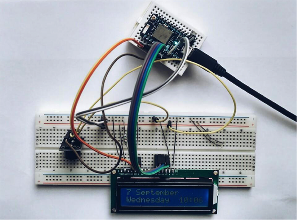
vi. Once you are done preparing the hole grid board, soldering the display to the Pi is up next. Grab your colored wires and cut them to a length of about 10cm. Put the display centered into the top row of holes. Check the adafruit tutorials pinout page for details about the wiring. You need to connect four wires: 3.3V; GND and the two I²C pins: SDA and SCL. Consider the schematic diagram concerning the wiring of the display and the Raspberry Pi vii. Having the display and the raspberry pi successfully soldered and mounted on the hole grid board, your setup should look something like the last picture from above. viii. Now continue installing the corresponding Adafruit library
Take Apart WiFi Stick vii. Like shown on intro of this instructable, this project uses the "EDIMAX EW-7811UN Wireless USB Adapter". Of course it should be possible to use just any kind of WiFi USB Stick in this project, but keep in mind that we just tested the one described. viii. Now take apart the WiFi-stick by slightly lifting the plastic case at the flat side of the usb plug. You should be able to remove everything, such that you have the bare wifi board laying in front of you, like shown in the picture Soldering to Pis Test Pads ix. After taking apart the WiFi-stick you'll need to cut four wires to a length of about 4cm. Solder the USB connections to the Raspberry Pi Zero test pads like shown in the picture: x. Keep in mind, that it will not be possible to connect additional USB devices to the Pis micro USB connection after using the USB test pads. Once the soldering is done, plug in the Pis power supply and check if the connection is working. The WiFi-stick should start blinking a few seconds after plugging in the power supply. Wait until booting is done and establish a WiFi ssh connection. All further steps will be based on using a ssh connection like this. In order to check your internet connection and update your Pi to the latest Raspbian version, type: sudo apt-get update
sudo apt-get upgrade
Configuring Multiple WiFi Connections (Optional) xi. If you plan to use your device in multiple networks you'll need to configure them first. By just using one WiFi connection you might just skip this step. Adding additional network connections you need to modify the file /etc/wpa_supplicant/wpa_supplicant.conf. Therefore type:
Note : Find the best solution for electronics components and technical projects ideas
keep in touch with our social media links as mentioned below
Mifratech websites : https://www.mifratech.com/public/
Mifratech facebook : https://www.facebook.com/mifratech.lab
mifratech instagram : https://www.instagram.com/mifratech/
mifratech twitter account : https://twitter.com/mifratech
Contact for more information : [email protected] / 080-73744810 / 9972364704