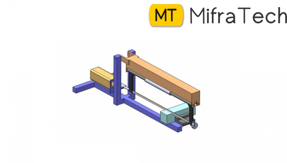
Pneumatic Operated Double Hacksaw Project
A hacksaw is a fine-toothed saw, originally and mainly made for cutting metal, plastic or wood. For industries to realize the production, it is necessary to cut metal, plastic bars with high rate. So, it’s not possible to depend on typical single frame power saw machines and wish the advance in technology and style of such machines. To automate the conventional power hacksaw machine in order to achieve high productivity of workpieces, we have proposed a power hacksaw machine which uses pneumatic power. The high-speed saw machine contains a bonus of high operation, the saw utilized in this can be used for specified needs and can be used to cut consistent with the necessity. The pneumatic operated double hacksaw is the plastic cutting machine tool designed to cut plastic by applying pneumatic pressure. Hacksaws are used to cut thin and soft metals, plastic. This pneumatic double hacksaw machine consists of rods for guiding hacksaw, Crank, stand base frame. Guide plate pushes second link. Pneumatic cylinder and other linkage are arranged so that it will actuate two hacksaw blades. Pneumatic operated double hacksaw machine can be used for cutting the wood, metal, pipe, angle, channel, flat plates, rods and such other things. It can be used in small scale industries and in large scale industries.
Components
ABSTRACT - This is an automation based cutting process, it consists of cutting of bar at certain distance. Bar, pipe or any shape pipe can be cut by using this machine without more effort and saving valuable time in manufacturing process. This machine has automatic clamping. Now days, there are wide verity of wire products like welding electrode, weld mesh, heat treated kitchen baskets, automobile spark plugs and exhaust valves etc. For manufacturing all above products, wire is used as primary element and is to be straightening from coil form. Now straighten wire is to be cut into wire rod as per required length. For these sequential operations, wire straightening cutting machine is used. Now days, conventional type wire straightening cutting machine are being used in which wire is cut by stopper cutter head which is limited by its length as well as feeding speed. This machine can be widely applied in almost all type of industries. The pipe cutting process is a main part of the all industries. Normally the cutting machine is manually hand operated one for medium and small scale industries. In our project is pneumatically operated Typical Pipe Cutting Machine. Automation in the modern world is inevitable. Any automatic machine aimed at the economical use of man, machine, and material worth the most. In our project is hand operated D.C valve and flow control valve is used for semiautomation. The pipe cutting machine works with the help of pneumatic double acting cylinder.
INTRODUCTION - Our wide range of tube and pipe cutting machines includes machines that can handle small or large diameter tubes and that can be equipped with powerhacksaw. We supply pipe cutting machines for round, elliptic or conical pipes as well as fully automated equipment featuring integrated logistics, or simpler, mobile versions. Pipe cutting machines are popular in offshore, pipe processing, ship building, pressure vessel, structural and mechanical contracting manufacturing because of the complex cuts and profiles typical required in their respective industries. Pipe cutting, or pipe profiling, is a mechanized industrial process that removes material from pipe or tube to create a desired profile. Typical profiles include straight cuts, mitres, saddles and midsection holes.
OBJECTIVE
1. Reduce cost of automation.
2. To increase productivity, save time and energy.
3. Feeding pipe and circular rod automatically.
4. Job feeding takes place during return stoke of the machine there by reducing the idle time further..
5. Automatic clamping and decamping by using sensor.
6. Minimal human intervention only limited to replacing the bar stock on to the machine.
A) CUTING STROKE - In first position of 5/2way DC valve, compressed air flows from P to A and B to El this flow is through flow control valve, the flow is controlled hence piston extends slowly and cutting stroke is complete. B) RETURN STROKE- In second position of 5/2way DC valve, compressed air flows from P to B and A to E2 and then piston retracts at higher speed to save the time. METHADOLOGY [1] Cutter motor: Cutter motor is 100 watt motor variable speed 0 to 8000 rpm. The feeding action is done by a double acting pneumatic cylinder speed of the piston in forward direction i.e, the cutter feed is controlled flow gradual cutting action using a flow control valve in circuit. [2] Job clamping and guide arrangement: Job is guided in the job guide whereas the clamping is achieved using a set of clamps. whereas the movable jaw is connected to another pneumatic cylinder which is operated to the cutter feed cylinder. [3] Job Feeding and sensing arrangement: For the semiautomatic version of the machine the feeding action is manual i.e. the job is feed in the job guide manually upto stooper., the proximity sensor is used to sense the job. [4] Proximity sensor and electrical circuit: Proximity sensor and the electronic circuit is a simple electrical circuit used to sequence the operations in the circuit. [5] Pneumatic circuit: Pneumatic circuit uses double acting pneumatic cylinders, one 5/2 way direction control valve and one flow control valve., functions of the above components have already being explained above. DESIGN ANALYSIS -- Torque Analysis - Torque given by spindle P = 2πNT/60 Where, P – Power in watt T – Torque given by spindle in N-mm N – Revolution of cutter in rpm T = 850x60/2πx11000 Tact = 0.7379 N-m Tact = 737.9 N-mm Consider 25% overloading Tdesign = 1.25 x Tactual Tdesign = 1.25 x 737.9 Tdesign = 921.25 N-mm
Design of Spindle
T = (π/16) x Fsxd3
921.25 = (π/16) x 56 x d3
d = 4.37
checking for shear stress
T = (π/16) x Fsxd3
921.25 = (π/16) x Fs x 4.373
Fs = 56.22 N/mm2>permissible shear stress
So, design is unsafe
Now, consider diameter of spindle d = 8mm
T = π/16 x Fs x d3
921.25 = π/16 x Fs x 83
Fs = 9.16 N/mm2<permissible shear stress
So, spindle is safe under torsional load
Shear stress in threaded end due to axial load :-
Piston rod threading end = M4 x 0.8 pitch
We Are Providing Free Guidelines On Latest Mechanical Projects.
we help with any kind of ece, cse, ise, and mech projectes on imbedded final year projects
final year project for ece
final year project for electrical and electronics
final year project of electrical engineering
We are top among top final year engineering projects developer in town. We Provide Final Year Projects For: CSE, ECE, Mechanical, Automobile, Diploma, Engineering and M.tech students.
Contact Us
#2232,3rd floor,16th B Cross, Near new town bus Stop, Opp to Hdfc ATM,Yelahanka New Town,Bangalore-64
We are leading projects all over Karnataka
PLEASE CONTACT FOR MORE DETAILS
Ph.: +91 9972364704
mechanical final year projects
mechanical engineering final year projects on automobile
mechanical engineering final year projects on thermal
mechanical engineering final year projects on agriculture
buy mechanical final year projects
mechanical engineering final year projects pdf
mechanical final year design project
mechanical engineering final year project ppt
m.tech mechanical final year projects
agriculture based mechanical engineering final year projects
final year projects for mechanical engineering related to automobile
mechanical engineering final year project analysis
mechanical final year project buy
best mechanical final year projects
final year mechanical projects done by iit students
buy final year projects for mechanical engineering
b.tech final year projects for mechanical engineering pdf
mechanical engineering final year project boiler
final year project for mechanical branch
final year mechanical engineering projects for college students
mechanical engineering projects for final year students low cost
mechanical engineering final year project
mechanical engineering final year project pdf download
mechanical engineering final year project ideas pdf
mechanical engineering final project pdf
final year design project mechanical engineering