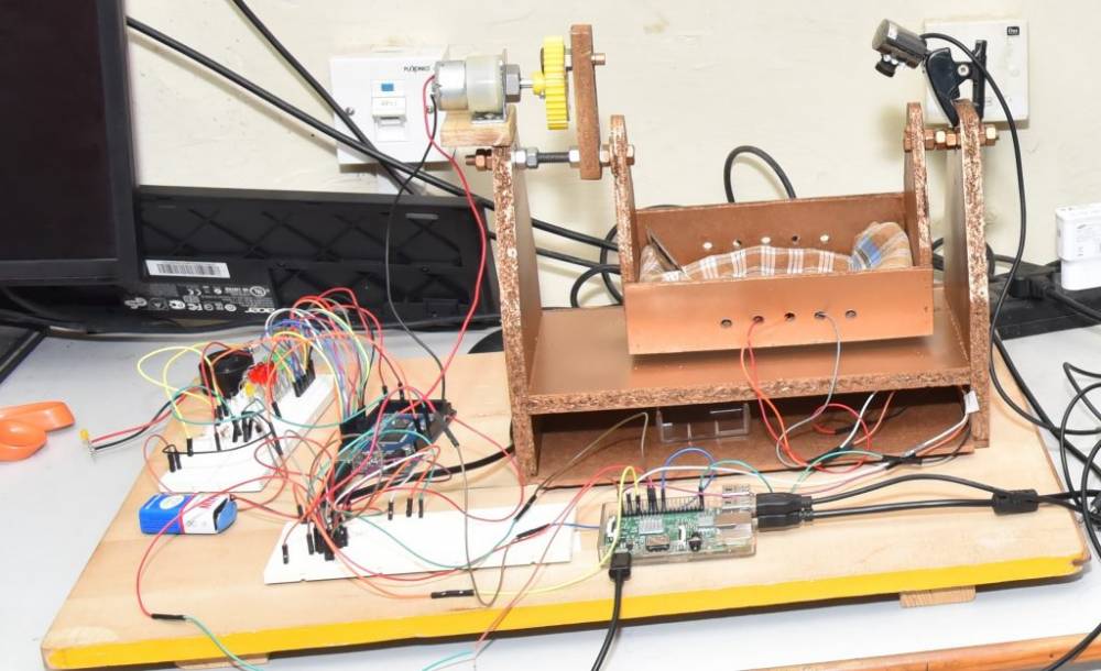
In the age of modernization, A Parent’s life undergo various changes due to child monitoring. Our project focuses on the relevant problems faced by parent in monitoring and nurturing their child while working. This project aims at reducing the challenges faced by parent by developing an IOT based Smart Cradle monitoring System that will assist Parent in monitoring their child. This cradle is equipped with an swinging mechanism which swings automatically on detection of baby crying sound. This proposed smart cradle has been integrated with an camera to provide continuous surveillance to parents. An arduino, sound sensors, wetness sensor, swinging mechanism along with other electronic components are used to upgrade existing cradle to meet the Present day requirements. This project is quite efficient and reliable which can deliver result better then conventional cradle.
INTRODUCTION
From last few decades there is a large migration of people in metro cities in search of better job opportunities (specially women workforce). At present couples who both are working may find it difficult to give proper time and care to their baby. In corona times many people were working from home and it was difficult for them to balance workload and parenting, This put extra burden on parent, Situation aggravates when baby is ill where it require a constant monitoring which results in taking leave from works. This not only affect the career of parent but also put a stress on them so there is a need to reduce burden of monitoring and nurturing on parents. Our project is an innovative idea to resolve this problem by developing an automated smart cradle system using IOT to monitor and nurture child in an efficient way. We ought to create an IOT based smart cradle system to assist parent in monitoring of their child regardless of their presence whether they are at work or in home. This cradle system is equipped with an automated swing mechanism which will swing automatically on detection of baby crying sound also it has an certain time limit to send an notification to parent if baby don’t stop crying, Along with it has an wetness detector to detect the wetness of mattress and send SMS to parent’s phone. A camera is attached at top of the cradle so that parent can have continuous surveillance on their baby while they are at work. This cradle also has an automatic toy for baby’s entertainment which will reduce the possibility of baby crying.
LITERATURE SURVEY
The first automatic rocking cradle which swings side by side on a horizontal axis which replicate the motion same as achieved by human oscillation of cradle. Spring motors are used to provide oscillatory motion to crib. Springs motors are attached to the crib of cradle that produce motion same as human efforts. The spring motor is of any known type in which the gear –operating means is easily stopped when the slightest resistance or opposition to its movement is encountered, thereby providing on extremely safe device for use with small children or babies. The advantages of this system is cost effectiveness, safe for small babies as it has mechanism to stop swinging of crib whenever a resistance is occurred, require less human efforts and presence. The limitation of this system is it does not support video monitoring . Yang HU developed an algorithm to control the speed of motors based on the parameters obtained from baby monitoring this model help the user to control the speed of swinging on pattern of intensity of baby crying. In authors have designed a cradle system with an android app to monitor baby, which swings automatically after detection of baby crying sound. The principle behind this mechanism is that a sound sensor detect sound made by baby during crying and compare it to Preset value in microcontroller if sound made by baby is greater than preset value a signal is generated by microcontroller who activates the swing mechanism also an SMS sent to parent phone using GSM module. Additionally a camera is placed at top connected with cloud server so that parent can request video from camera from any place. In authors have used a Gas sensor (MQ-135), Temperature sensor (LM-35), sound sensor (KY-038) and a cloud server to integrated it with Raspberry pi in order to upgrade the conventional cradle system to meet the needs of parents. The three sensors records the data collected from baby body parameters and all the information taken from sensors is stored in cloud which keep on sending SMS to parent regarding baby parameters at regular interval of time. This system is user friendly as it requires less hardware components and cost effective. The limitation of this system is that it only informs the parent about baby status but don’t take any action to make him/her stop crying. In introduced a framework which observe all necessary indication of the child like heartbeats and the internal heat level utilizing remote innovation and sound sensors which is used for observing the cry pattern of the child. Additionally, the live images of the infant is obtained through camera module through a Wide Area Network (WAN) which can be sent through mail and it can keep surveillance on the baby from distant areas around the world. The camera module is also induced which is responsible for observing the activities of the child and keeping an eye on the infants development in a limited area. This framework is easy to use and quite cost effective
COMPONENTS
The below section gives a detailed information about the components used in this project with their specifications.
1. Arduino Uno
Arduino Uno is a microcontroller board based on the ATmega328P. It has 14 digital input/output pins (of which 6 can be used as PWM outputs), 6 analog inputs, a 16 MHz ceramic resonator (CSTCE16M0V53-R0), a USB connection, a power jack, an ICSP header and a reset button. It contains everything needed to support the microcontroller; simply connect it to a computer with a USB cable or power it with a AC-to-DC adapter or battery to get started.
2. GSM Module
A GSM module is a a hardware device that uses GSM mobile telephone technology to provide a data link to a remote network. From the view of the mobile phone network, they are essentially identical to an ordinary mobile phone, including the need for a SIM to identify themselves to the network. GSM modems typically provide TTL-level serial interfaces to their host. They are usually used as part of an embedded system.
3. Servo Motor
A servo motor is a rotary actuator or linear actuator that allows for precise control of angular or linear position, velocity and acceleration. It consists of a suitable motor coupled to a sensor for position feedback. It also requires a relatively sophisticated controller, often a dedicated module designed specifically for use with servo motors.
4. Wet Sensor
It detects the moisture in crib when baby urinate and send signal to arduino.
5. Condenser microphone
A condenser microphone is an active transducer that converts sound waves (mechanical wave energy) into audio signals (electrical energy) via the movement of a diaphragm in a fixed-charge capacitor-based capsule and electrostatic principles
6. WIFI- Camera
A Wireless cameras work by transmitting the camera's video through a radio (RF) transmitter. The video is sent to a receiver that is connected to a built-in storage device or through cloud storage. Through your monitor or receiver, you'll have an easy link to access all of your image or video clips.
Interfacing and working of sound sensor with arduino
To detect the sound of baby during we need a sound sensor to detect the noise. A sound sensor is a electrical component used to detect the sound present in the near environment. A sound sensor have a microphone(50KHz- 100KHz) and a processing circuitry which converts analog sound waves into electrical signals. This electrical signal act as input to LM393 which is a High Precision Comparator that converts electrical signal into digital signal and send it to output pin. A sound sensor have 3 Pin: 1. VCC- This pin is used to provide power to sensor. Its operatonal voltage range is 3V – 5V. 2. GND - This Pin is used to ground the connection. 3. OUT – At this Pin final digital signal is obtained which is connected to arduino to feed it. When no noise is detected voltage across this pin is High and when noise is detected voltage across this pin becomes low. This pin can be connected to any of the 14 digital pin in arduino. Connect VCC pin of sound sensor to 5V on the arduino and GND pin to ground on arduino, OUT pin to digital pin 7 on the arduino. To detect the sound of baby accurately we need to calibrate the sensor by rotating knob or screw present at the top of the sensor, rotating screw in clockwise direction will decrease the sensitivity and rotating in anti clockwise will increase the sensitivity. Once sensor become calibrate to measure the sound of baby when crying accurately connection is done as mentioned above and sound sensor is ready to use
Interfacing and working of servo motors with arduino
Servo motors are used to produce oscillation motion because it is quite efficient, powerful and its parameters are easily adjustable to user need such as speed. Servo motors can be controllable by providing series of pulses to the signal lines. A conventional; servo motor expects pulse signal at every 20 milliseconds (i.e signal should be 50 KHz) 1. If the pulse is high for 1ms, then the servo angle will be zero 2. If the pulse is high for 1.5ms, then the servo angle will be at its center position. 3. If the pulse is high for 2ms, then the servo angle will at 180 degree. To replicate the swinging elevation of crib same as human swinging we need to fix the pulse at 1.5ms to avoid over elevation angle which increases the chances of baby to fall out from crib.
Interfacing GSM module and working with arduino
GSM (SIM900 GSM shield) module is used to send notification on parent phone and receive commands from parents with the help of cloud server. The Tx pin of GSM module is connect with RXo f arduino which is pin 0 and RX pin of GSM module with TX pin of arduino which is pin.
Note : Find the best solution for electronics components and technical projects ideas
keep in touch with our social media links as mentioned below
Mifratech websites : https://www.mifratech.com/public/
Mifratech facebook : https://www.facebook.com/mifratech.lab
mifratech instagram : https://www.instagram.com/mifratech/
mifratech twitter account : https://twitter.com/mifratech
Contact for more information : [email protected] / 080-73744810 / 9972364704