
You all will agree with the fact that high energy consumption by our household appliances is quite bothering and each month we make every possible effort to reduce the electricity bill. Not just that, in the quest to understand and monitor the power usages, we keep checking electricity meters installed in our home/offices. What if we can monitor the electricity bill from anywhere on our smartphones? Yes, with the help from the Internet of Things, we can easily monitor power consumption using a smart energy meter.
For quite some time, I have been trying to find out ways to build a simple yet accurate way to measure and monitor the power usages from anywhere, be it at home office or on the go. After some research, I decided to build a simple one by using a current sensor with NodeMCU This can be done with the help of the Adafruit MQTT IoT Platform which is free and doesn’t require a subscription. To build this energy meter, you will only need very few components and an internet connection.
There are many ways to measure the current flowing through a wire, the popular current sensing methods are discussed here. The current sensing is done in two ways, namely the Direct sensing method and the indirect sensing method. Direct sensing method uses Ohm’s law to measure the voltage drop occurring in a wire when current flows through it, but ACS712 uses indirect current sensing method (which is measured by calculating magnetic field by applying either Faraday’s Law or Ampere’s Law), hence there will be no external load on the current-carrying wire and no direct contact is needed. It is similar to how clamp meter works. We will discuss more on ACS712 working later in this article.
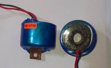
Another popular method for Current sensing is using a Current Transformer (CT). It is also an indirect current sensing method. It also works in the same way where the carrying wire passes through the center hole of CT transformer and the CT transformer consists of a coil that will pick up the magnetic flux generated by the current-carrying wire. By measuring the voltage induced in this coil, we can calculate the current that passed through the wire.
ACS712 is based on the theory of Hall effect which was discovered by Dr. Edwin Hall in 1879. According to the principle, when a current-carrying conductor is placed in the magnetic field, a voltage is generated across its edges perpendicular to the direction of both current and the magnetic field. This voltage is known as hall voltage and its typical value is in the order of few millivolts. So by measuring the Hall voltage, we will be able to calculate the amount of current flowing through the sensor. A typically ACS712 Current sensor is shown below.
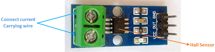
When an electron flows through a wire or path, it creates a magnetic field in its surroundings. This magnetic field is sensed by the Hall effect IC and a voltage output is produced which can be directly fed into the microcontroller or ESP board. This sensor is located at the surface of the IC on a bold copper conducting path from phase input-output.
ACS712 sensor has 4 variants (185mV=5A module,100mV=10A & 66mV for 20A & 30A module) and each variant is rated is for a different current value. You can choose any of them as per your requirement but for better calibration, millivolts per Amp value should be correctly assigned to the coding. Note that as the current rating of the sensor increases, the accuracy will decrease.
The complete circuit diagram for IoT based Energy Meter is shown below. Although it is very simple, you should follow the graphical representation for a better understanding and make sure the connections are correct. Be advised that working with mains requires practice and hence do not build this circuit if you are not sure how to do it.
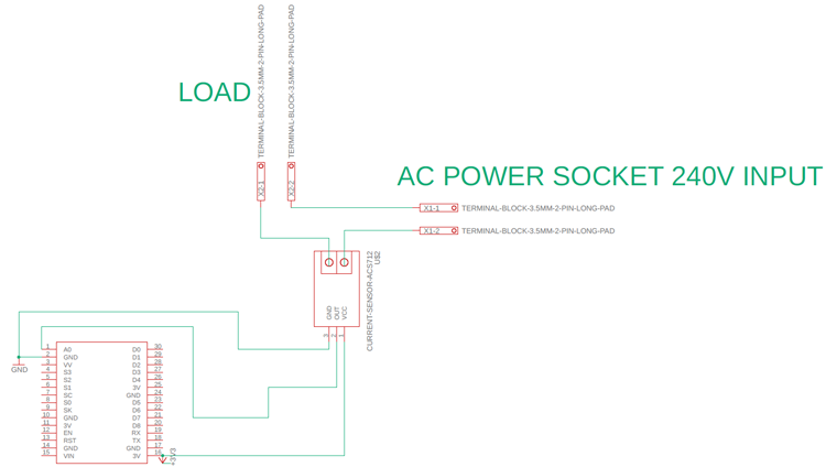
We have used NodeMCU with ACS712 Current Sensor, the current sensor will measure the current consumed by our AC load and the NodeMCU will measure this current, calculate the power (assuming the voltage is constant) and send the power value to a cloud platform like Adafruit IO. A visual info-graphic circuit diagram is also given below for your convenience.
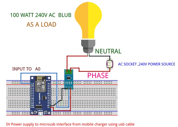
As you can see the NodeMCU will be powered through the USB port using a 5V mobile charger and the AC load will be connected to the 220V AC mains through our ACS712 current sensor.
The sensor has a maximum input voltage on VCC is 5V but it also works fine in lower voltage. Please note that the ASC712 output offset voltage is dependable on its operating voltage (generally half of the operating voltage). Since we powered up the module from the ESP 3V output pin the ACS712 module output offset voltage is 1.5 volt (1500 mv) when there is no current flowing. ESP has an onboard voltage divider circuit internally, so we are giving direct input from ACS712 output to the A0 input pin.
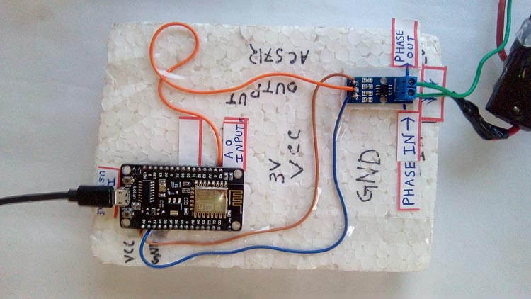
Make the connections as shown in the circuit above. I directly soldered the wire between the NodeMCU and ACS712 sensor but you can also use a breadboard and connecting wires. My setup looks like this below when ready.
CONCLUSIONS
The proposed system is able to reduce the sufferings of the customer and make users concern about the excessive consumption of electricity as well as faulty devices at home. Through this system, customers can easily view total pulse, total units and total costs of electricity. The system is easily readable and reliable. The data stored in the cloud has great importance in future energy meter data mining. In a large sense, energy distribution company such as DPDC able to observe the pattern of consumption of an area. Consequently, this observation can help in load distribution in a certain area.
Note : Find the best solution for electronics components and technical projects ideas
keep in touch with our social media links as mentioned below
Mifratech websites : https://www.mifratech.com/public/
Mifratech facebook : https://www.facebook.com/mifratech.lab
mifratech instagram : https://www.instagram.com/mifratech/
mifratech twitter account : https://twitter.com/mifratech
Contact for more information : [email protected] / 080-73744810 / 9972364704