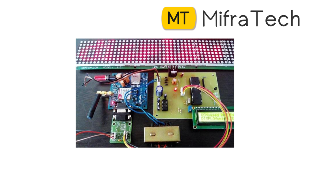
We know the importance of notice boards in public places like railway stations, bus stations and airports. But changing notices day-to-day is a difficult task. This article explains you how to design a Wireless Electronic Notice Board using GSM technology. The project displays the data on LCD whatever we sent from the mobile.
There are many wireless communication technologies like Bluetooth, RF Communication, ZigBee, etc. but GSM Technology based communication allows long range, reliable and secure communication.
The Wireless Electronic Notice Board using GSM project, as the name suggests, is built around GSM Technology as mobile phones (that communicate through GSM Technology) have become very abundant, cheap and easy to use.
When we send the message from the mobile, the GSM Modem which is connected to the Microcontroller and the display unit, will receive the message. Now, the microcontroller reads the message from the GSM Modem and displays it on LCD.
When user sends the message from the mobile, GSM modem sends the below command serially to indicate that a new message is received.
+CMTI: “SM”,3
In the above command, number “3” indicates the location of the new message i.e. it is the third message in the inbox. Now you need to read this unread message to display on LCD. The command to read the message from GSM modem is
AT+CMGR=3
Here, the number “3” indicates the location of the message to be read. After giving this command to the GSM module, it will send the below command serially.
+CMGR: “REC UNREAD”,”MD-WAYSMS”,,”13/05/20,15:31:48+34″
Electronics Hub
In the above command, “REC UNREAD” indicates that message is unread message, “MD-WAYSMS” indicates sender mobile number or name, 13/05/20 indicates the date, 15:31 indicates time and Electronics hub is the content of the message.
From the above command we need to extract message (Electronics Hub) sent by the user to display it on the notice board (LCD).
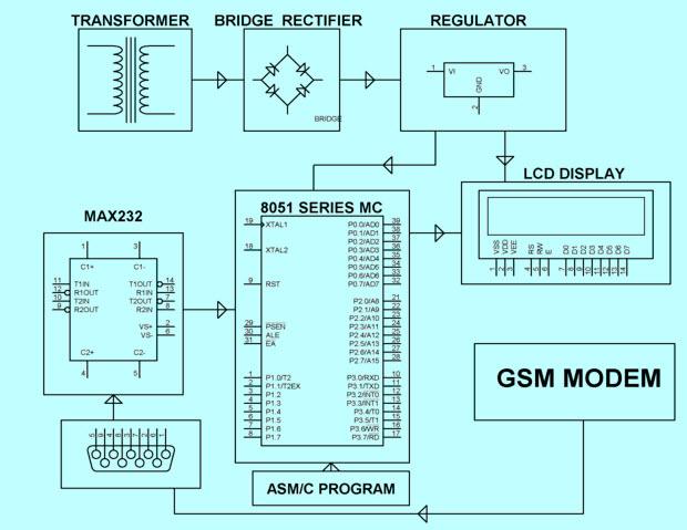
The above circuit of the Wireless Electronic Notice Board using GSM consists of, GSM Module (Modem) and 16 x 2 LCD. Here, the 16 x 2 LCD is used to display message and is used in 8 – bit mode. Means, we need 8 data lines to display the data. The data lines of the LCD Display are connected to PORT1 Pins. The control pins RS, RW, and E pins are connected to P3.6, GND and P3.7 pins respectively.
The GSM Module is directly connected to the microcontroller as the logic levels of both the GSM Modem and Microcontroller are already matched in the GSM Module Board. If there is no level converter on the board, then we need to use MAX232 level converter as a mediator between Controller and GSM to transfer the data.