Emerging technologies are making our life simpler these days. With the introduction of mobile phones, life has changed rapidly. This is a dream of radio engineering. Mobile phones merged land line telephone systems. These days, many advancements in the mobile phones were introduced.
These advancements provide many services such as text, internet etc. But although there are many advancements in the technology, we still rely on the wired battery chargers. Each phone will have its own designed battery charger. Thus the battery chargers are required to carry everywhere to keep the battery backup. Now just think of a battery charger that charges your mobile automatically. When you sit for tea and place your mobile on the table, it simply charges your mobile. This article explains a simple wireless battery charger circuit that charges your mobile when placed near the transmitter. This circuit may be used as wireless power transfer circuit, wireless mobile charger circuit, wireless battery charger circuit, etc.
This circuit mainly works on the principle of mutual inductance. Power is transferred from transmitter to the receiver wirelessly based on the principle of “inductive coupling”.
Inductance is the property of the conductor, in which the current flowing in a conductor induces a voltage or electromotive force in it or in another nearby conductor. There are two types inductance.
1) Self inductance,
2)Mutual Inductance.
“Mutual inductance” is the phenomena in which, when a current carrying conductor is placed near another conductor voltage is induced in that conductor. This is because, as the current is flowing in the conductor, a magnetic flux is induced in it. This induced magnetic flux links with another conductor and this flux induces voltage in the second conductor. Thus two conductors are said to be inductively coupled.
Wireless battery charger circuit design is very simple and easy. These circuits require only resistors, capacitors, diodes, Voltage regulator, copper coils and Transformer.
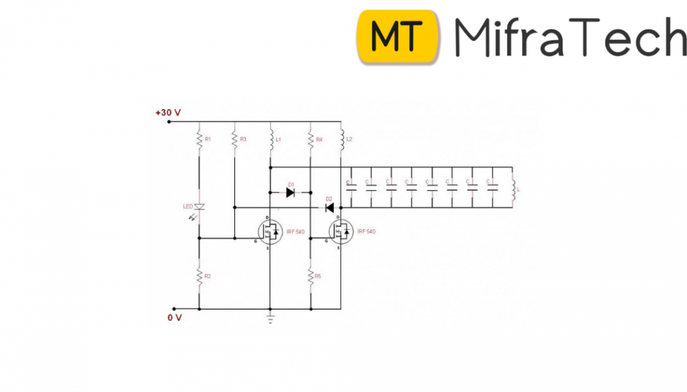
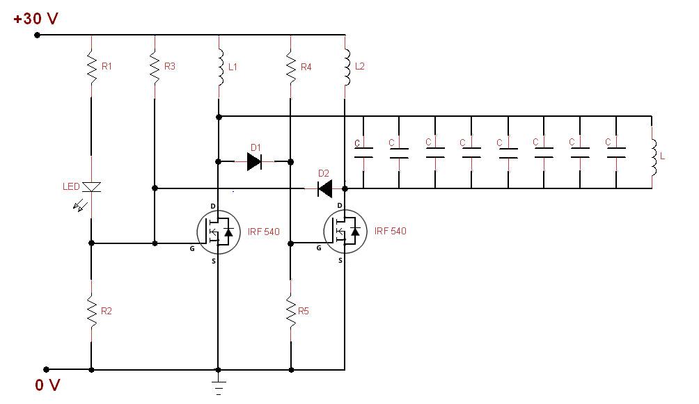
In our Wireless battery charger, we use two circuits. The first circuit is transmitter circuit used to produce voltage wirelessly. The transmitter circuit consists of DC source, oscillator circuit and a transmitter coil. oscillator circuit consists of two n channel MOSFETS IRF 540 , 4148 diodes. When the DC power is given to the oscillator, current starts flowing through the two coils L1, L2 and drain terminal of the transistor. At the same time some voltage is appeared at the gate terminals of the transistors. One of the transistors is in on state while the other is in off state. Thus voltage at drain of transistor which is in off state raises and it fall through the tank circuit made of 6.8nf capacitors and transmitter coil of 0.674. Thus operating frequency is determined by using formula F=1/[2π√(LC)].
In the second circuit that is receiver circuit consists of receiver coil, rectifier circuit and regulator. When the receiver coil is placed at a distance near the inductor Ac power is induced in the coil. This is rectified by the rectifier circuit and is regulated to DC 5v using 7805 regulator. The rectifier circuit consists of 1n4007 diode and capacitor of 6.8nf. The output of regulator is connected to the battery.